

Reliable Current Sensing Resistor Which One to Trust
2026-09-23
Every millivolt counts when your circuit's stability hangs in the balance—so why do so many engineers settle for unreliable current sensing resistors? The market is flooded with options that promise precision but deliver drift, noise, and thermal headaches. Before you trust your next design to guesswork, ask yourself: which resistor will actually hold its accuracy when it matters? Milliohm cuts through the noise to help you separate the trustworthy from the merely tempting.
How to Tell If a Current Sense Resistor Will Stay Honest Over Time
Long-term drift in current sense resistors rarely announces itself with a bang. It shows up as a slow bias in your current readings, usually after the board has seen hundreds of thermal cycles. Look beyond the initial tolerance spec and ask for the resistor's load-life stability curve under your actual operating temperature range. A part that shifts more than 0.5% after 1,000 hours at rated power is likely to keep wandering when it lives on your PCB for years.
The real test is how the resistive element handles thermal expansion mismatches. Metal foil and bulk metal elements tend to hold their value far better than thick film, which relies on a glass-metal matrix that can micro-crack under repeated stress. If you can, cross-section a stressed sample and check for crack initiation near the termination. That's where drift begins, not in the middle of the element.
Also pay attention to the solder joint and pad design. Uneven current distribution across the termination can create localized hot spots that accelerate aging, even if the resistor's own datasheet claims excellent stability. A well-designed four-terminal Kelvin connection will not fix a resistor that drifts, but it will keep you from mistaking board-level variation for component drift when you finally do the failure analysis.
The Temperature Coefficient Trap Nobody Talks About
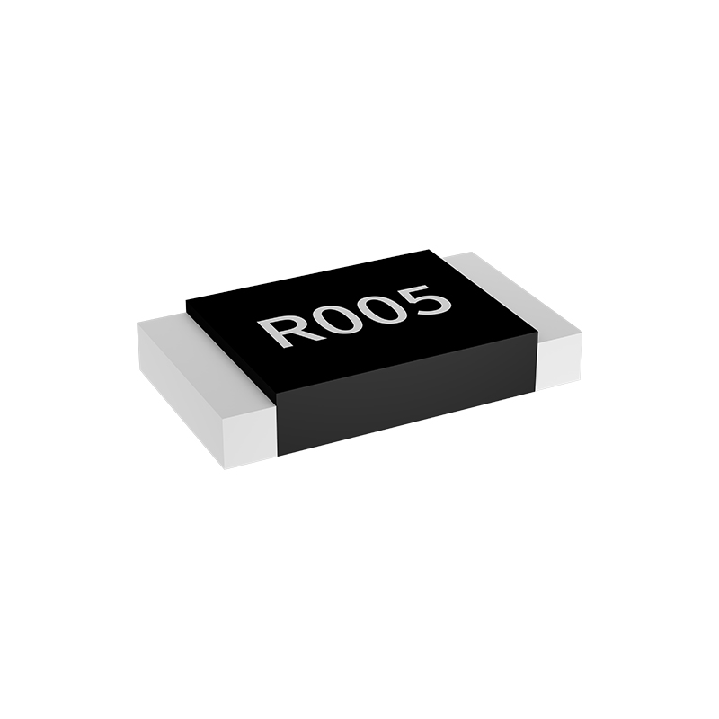
Most designers glance at the temperature coefficient on a datasheet, note that it’s small, and move on. That single number, usually expressed in ppm/°C or %/°C, feels like a footnote. But here’s the part nobody mentions: that coefficient is not a fixed property. It shifts with the operating point, the thermal history, and even the soldering profile you used. A resistor rated at ±50 ppm/°C might behave like ±15 ppm near room temperature but drift to ±80 ppm once the board warms up under load. When you’re counting on a stable gain or a precise reference, that nonlinear drift becomes a silent error source that no simulation model will show you.
The trap gets deeper when you realize that most temperature coefficient specs are averaged over a wide range, not guaranteed at the exact temperatures your circuit actually sees. A voltage regulator’s output might be specified as 100 ppm/°C from -40 to +125°C, but if your device idles around 65°C, the local slope can be three times worse. And it’s not just passive components—op-amp input offset, ADC reference, even the copper traces on your PCB have their own temperature behavior. Pair a “low drift” amplifier with a “precision” resistor whose curves bend in opposite directions, and the combined error can swamp your entire noise budget. That’s why field failures often trace back to a lab bench where the air conditioning masked a thermal runaway.
The way out isn’t to chase zero drift—it’s to measure the actual coefficient curve for the components you’re actually shipping. Bake a few boards, log the shift, and plot the error versus temperature at your worst-case load. You’ll often find that a cheaper part with a flatter local curve beats an expensive one with a slightly better average spec. And remember that thermal gradients across the PCB matter as much as the component’s own rating: a resistor sitting next to a hot LDO will see a different local temperature than the thermocouple on your test jig. Until you acknowledge that the datasheet number is just a hint, not a promise, temperature will keep quietly eating your margins.
Datasheet Claims vs. Bench Reality: A Closer Look
Manufacturers love quoting peak figures that rarely survive contact with an actual test bench. A CPU might be listed with a 5.7 GHz boost clock, but that number assumes a single core under ideal cooling, a short burst window, and a motherboard that ignores default power limits. The moment all cores light up in a sustained render or a game that leans on the processor, clocks drop by several hundred megahertz, and the promised performance evaporates. The gap isn't always dishonesty—it's the difference between a clean-room lab and the inside of a cramped case with dust filters and a mid-range air cooler.
Graphics cards play the same game with TDP and boost behavior. A spec sheet might claim a 320 W board power, yet in practice the card pulls 380 W for minutes at a time if the thermal headroom allows. That extra power can translate to higher clocks than the official boost rating, but it also means louder fans and hotter memory modules. Conversely, when thermals get out of hand, the same card can fall below its advertised clock, delivering frames that don't match the review samples sent to press. Real-world benches with an open-air test rig versus a closed chassis often show a 3-5% swing in frame times, which is far more meaningful than the 1% difference on paper.
Storage is another area where printed numbers mislead. A drive's sequential read speed of 7,000 MB/s looks impressive on a box, but everyday workloads are dominated by random reads at low queue depths and mixed writes that hammer the controller's firmware. After the SLC cache fills up—usually within a minute of a large file transfer—write speeds can drop to a third of the rated value. The only way to know is to run a sustained transfer test, not the 10-second burst used for marketing. Benchmarks that mirror actual tasks—boot traces, game load sequences, video editing timelines—consistently show less variation between a budget NVMe drive and a flagship model than the specs suggest.
Load Cycling and Thermal Fatigue: The Silent Resistor Killers
Resistors rarely fail from a single dramatic event. Instead, they wear down under the steady rhythm of power cycling. Every time a board powers up, current flows through the resistive element and local temperature climbs. On shutdown, it cools again. The ceramic core, resistive film, and metal terminations all expand and contract at slightly different rates. After enough cycles, that mismatch begins to tear the film away from the core or crack the end caps. Datasheets won’t warn you because no individual temperature swing looks dangerous — but the accumulated strain is very real.
Load cycling is especially harsh when a resistor runs well below its rated power but gets switched on and off frequently. A hot spot forms near the center of the element while the ends stay cooler. That temperature gradient produces repeated mechanical stress, and the solder joints at the terminations are usually the first to give way. Lead-free solder makes matters worse because it is stiffer and less forgiving than tin-lead. Microcracks open and close with each cycle, and resistance begins to drift upward in small, irregular steps.
Thermal fatigue often masquerades as an intermittent fault. A hairline crack might close when the board is warm and separate when it cools, so the failure disappears during bench testing. In pulse applications, even low average power can create localized hot spots that accelerate electromigration and grain growth inside thick-film resistive material. The value shifts slowly over thousands of hours, and by the time the error is noticed, the resistor has already been operating outside tolerance for months.
Construction Materials That Make or Break Current Sense Accuracy
The heart of any current sense resistor is the resistive alloy, and not all alloys behave alike under real load. Manganin and ZERANIN are popular because their thermal EMF against copper stays low, but their mechanical hardness and annealing schedule decide whether that low EMF survives repeated pulse stresses. Thick film pastes often rely on a glass binder that can micro-crack near the termination edge, creating hot spots and a measurable shift in resistance that doesn't recover. Bulk metal foil elements, cut from a single sheet and then mounted, avoid many of those grain-boundary weaknesses but pick up strain from the adhesive layer beneath them.
Termination and lead-frame materials often get overlooked, yet they sit directly in the measurement path. A copper lead frame with a nickel barrier and tin finish can generate its own thermocouple junctions—each material transition becomes a tiny voltage source when a temperature gradient forms across the resistor. The length and plating thickness of the end caps matter just as much as the alloy choice, because uneven solder fillets or mismatched pad materials on the PCB create asymmetric heat flow that shows up as offset drift.
Protective coatings and substrate choices add another layer of error. An alumina substrate offers good thermal conductivity but its expansion coefficient can pull a bonded foil element into micro-strain after every thermal cycle, shifting the baseline resistance. Conformal coatings or molding compounds that absorb moisture introduce leakage currents that bypass the sense element altogether, especially in high-humidity environments. The simple rule is that every material touching the resistor—from the internal adhesive to the outer solder mask—shares responsibility for the final measurement accuracy.
What to Ask Before You Trust a Resistor for the Long Haul
Selecting a resistor for a design that must hold up over years of service goes far beyond checking the nominal resistance value. You need to dig into how the part behaves when pushed to its limits, because the environment inside a real enclosure rarely matches the datasheet's room-temperature comfort zone. A resistor that looks perfect on paper can drift, crack, or fail quietly if you never asked the right questions about its long-term behavior.
Start by questioning the power rating and how much headroom you actually have. Many engineers pick a resistor with a wattage rating just above the calculated dissipation, but that leaves no margin for hot spots, reduced airflow, or aging of nearby components. Ask whether the resistor can survive continuous operation at 70% or 80% of its rated power without the resistance shifting beyond your tolerance. Also check the temperature coefficient and how it interacts with your circuit's operating range — a part that is stable at 25°C can wander noticeably at -40°C or +105°C if the tempco is too high.
Finally, look at the failure modes and long-term drift data. Thin film, thick film, wirewound, and metal foil resistors all age differently under thermal cycling, humidity, and voltage stress. Ask the manufacturer for accelerated life test results or field failure rates, not just a generic MTBF number. A resistor with a lower initial cost might end up costing far more if it drifts out of spec after a few thousand hours in a damp or vibration-heavy environment. Trust comes from knowing how it will behave in year five, not just on day one.
FAQ
Reliability hinges on a combination of low temperature coefficient of resistance (TCR), tight tolerance, and stable long-term drift under thermal cycling. You also want a robust element material like bulk metal foil or thick film with a proven power derating curve.
Shunts offer higher accuracy and lower cost for smaller currents but add insertion loss and heat. Hall sensors provide galvanic isolation and handle large currents without voltage drop, yet they suffer from offset drift and lower bandwidth. Pick based on isolation needs and acceptable power loss.
Through-hole wirewound or metal element resistors with compliant leads handle flex better than surface-mount thick films. For SMD, choose a wide terminal type or a Kelvin 4-terminal design that reduces stress on the solder joints and element.
Often it's due to localized hot spots from uneven current density or poor PCB thermal relief. Also, repetitive thermal expansion mismatches between the resistive element and substrate can cause microcracks. Always verify pulse power ratings and use a low-thermal-EMF layout.
When you measure below roughly 100 milliohms or need accuracy better than 1%, the separation of current and voltage terminals eliminates lead resistance errors. It's also essential for high-current paths where PCB trace resistance would otherwise ruin your measurement.
Rarely. Thick film resistors have noticeable TCR and can shift value after soldering heat. For battery gauging where every millivolt counts, use a metal alloy or foil resistor with TCR under 50 ppm/°C and a stable, low-ohmic value like 5 to 20 milliohms.
Thermal EMF between the resistive element and copper leads creates a small voltage offset that changes with temperature gradients. This reduces measurement accuracy at low sense voltages. Choose resistors made with low-thermal-EMF materials like manganin or Evanohm, and keep both terminals at the same temperature.
No single brand dominates across all applications. However, Vishay's WSL series, Bourns' CRA series, and Ohmite's metal element parts frequently appear in reliable designs. Trust comes from matching the resistor's pulse handling, TCR, and physical size to the actual load profile rather than relying on a brand name.
Conclusion
The quest for a dependable current sense resistor often starts with spec-sheet bravado and ends with a drift you didn't see coming. Time and temperature have a way of exposing the gap between a manufacturer's promise and what happens on your bench. If you want a part that stays honest, stop fixating on initial tolerance alone. The real question is whether the resistive element and its terminations can shrug off repeated load cycling without micro-cracking, delaminating, or quietly shifting value. Thermal fatigue rarely announces itself; it shows up weeks or months later as an offset you can't calibrate away.
Materials matter more than most designers admit. Metal foil and certain bulk metal alloys tend to hold their shape under stress, while thick-film parts often hide temperature coefficient quirks that only appear under transient heating. Before trusting any resistor for the long haul, push it beyond the typical room-temperature characterization. Cycle it hard, watch the cold resistance return, and ask pointed questions about construction, not just numbers. A truly reliable current sense resistor earns its keep through honest behavior under thermal and mechanical strain, not through a well-worded datasheet.
Contact Us
Contact Person: Yuying Gao
Email: [email protected]
Tel/WhatsApp: +86 18926013721
Website: https://en.milliohm.net/